3d printed mountains
Introduction
Not to go full cooking blog in my description, but I wanted to give a shout out to the inspiration for this project. I was walking around the Oregon Convention Center during a winter craft festival and came across a booth with a really great local artist that goes by TimPlusApril. There were selling beautiful topographical map prints of Oregon mountains. They can be purchased here.
This inspired me to generate similar prints but through a 3D printer to really capture the shadows and peaks across these neat-o mountains.
There are a bunch of different tutorials out there for using LIDAR or other public domain topographical data to generate landscapes and city scapes for 3d printing. I wanted to try my hand at it for a minimalistic wall piece. This is the end result, with marble PLA glued to some cheap unfinished wood canvases. The whole project ended up costing a bit less than $10 per mountain. Support your local businesses if you can.
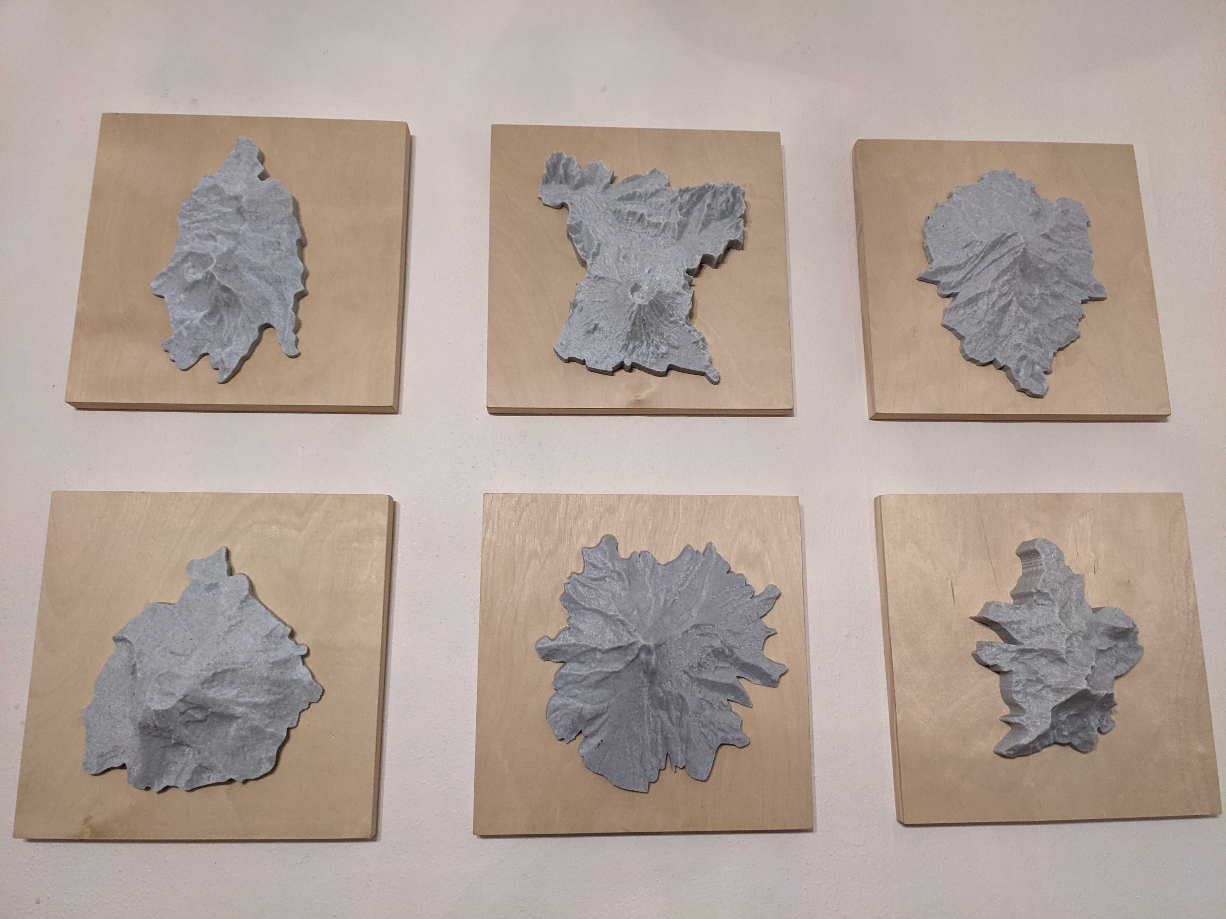
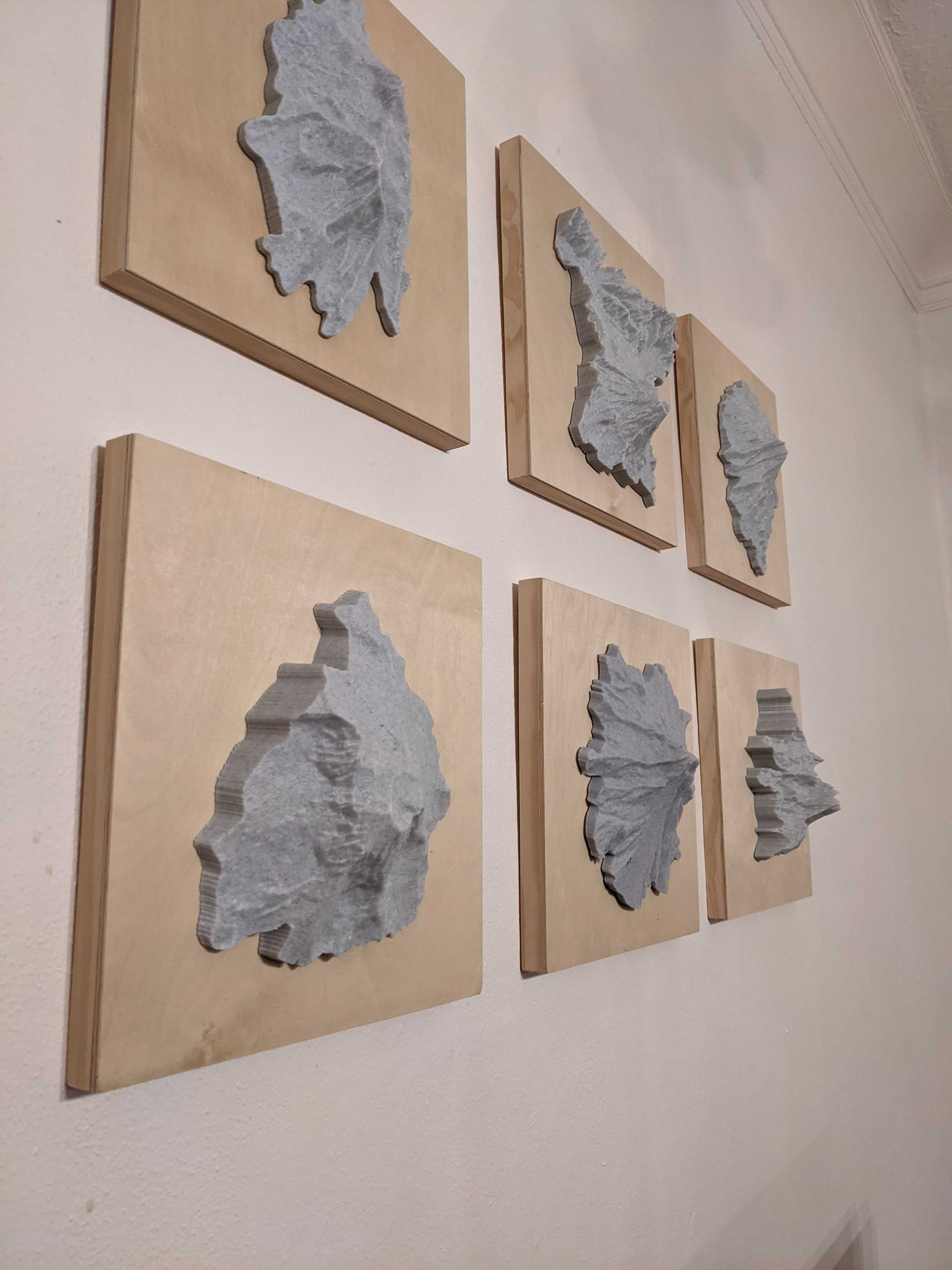
| Front View | Side View | Mount Hood Zoom |
|---|---|---|
 |
 |
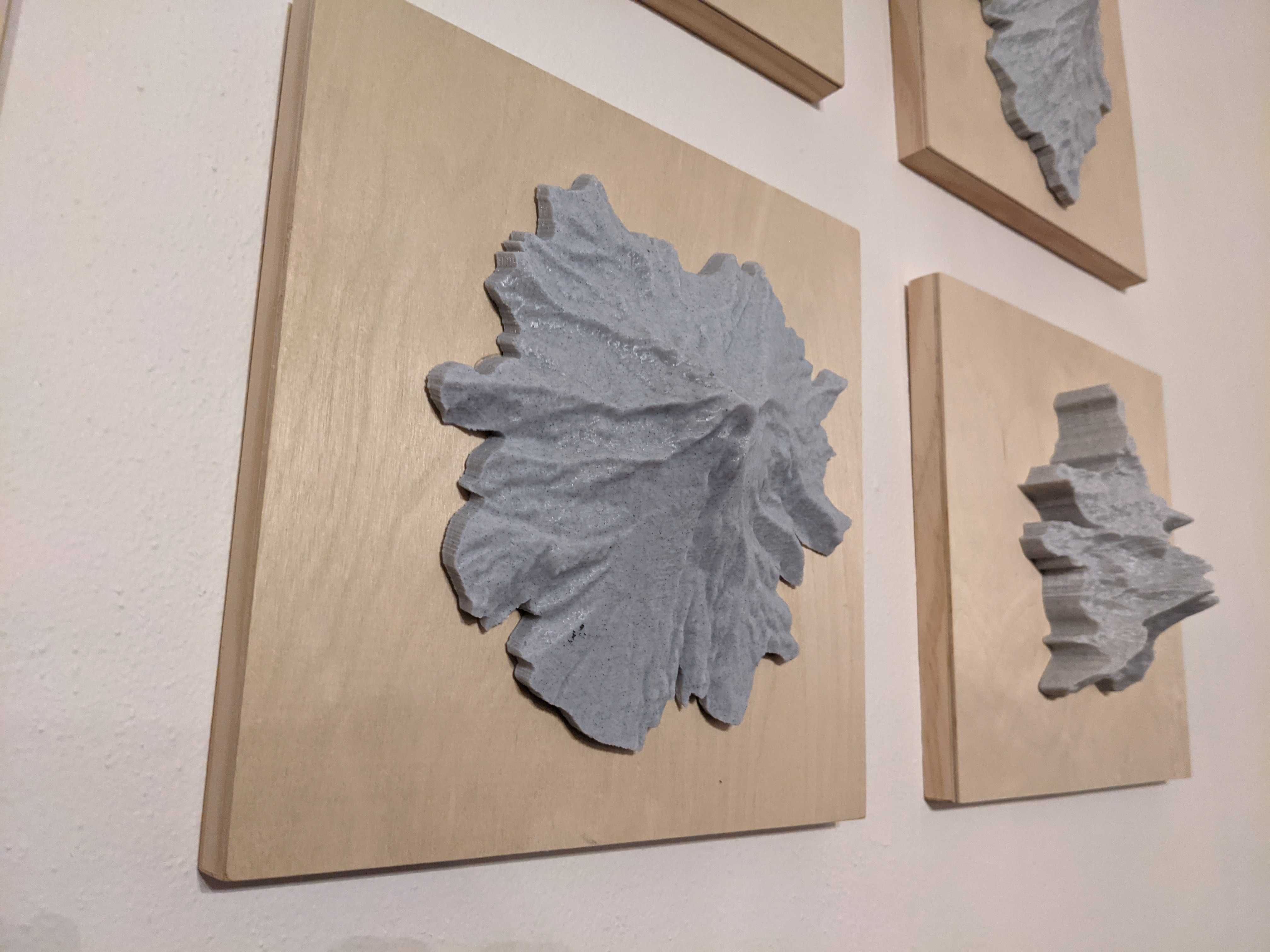 |
Mountains are (clockwise starting at top left): North and Middle Sister, Helens, Jefferson, Broken Top, Mt Hood, South Sister.
For this project you will need:
Required materials
- Marble PLA (link)
- Unfinished Wooden Canvases (I used 10”x10”; link)
- Command hooks for hanging (link)
- Wood Glue (link)
Required software
- Vector Graphics Software (I use adobe illustrator, but Inkscape works as a free substitute)
- Blender (link)
- BlenderGIS Plugin (link)
- PrusaSlicer (link)
Required equipment
- 3D Printer for PLA (I use an Ender 3)
Note: there are also tons of companies that will print things for you, but in the end just buying your own printer will end up being cheaper. Plus it opens the door for so many other projects!
Here I generated a gallery of GIFs showing the step by step process from start to finish. I’ll go into more detail below. If you want to skip the tutorial, I am also hosting the STL files on my GitHub page.
3D Mount Hood Topography
Gif numbers (1-14) are listed as separate steps below with more information. If you want to pause them, rewind, or zoom in, you can click on the widget and it should bring you to the Imgur gallery.
Generate an organic boundary for your mountain
1. Grab an image of the boundary you want.
Using Google maps I search for Mount Hood and do a simple screen grab to capture the area around Mount Hoods Peak.
2. Vectorize the image.
- In a vector editing software (I’m using Adobe Illustrator), paste the screen grab into a blank document.
- Then use “Image Trace” with a low amount of colors to vectorize the flat image.
I am going to use the white and brown to define the boundary in this tutorial. You can play around with sliders until you are happy with the vectorized output.
3. Remove the external vectors.
- Select the regions using the point selection tool (keyboard shortcut is “A”).
- Inverse the selection to highlight all the green regions and delete them (“Del”).
4. Simplify the boundary edge.
- Select all (“Ctrl+A”) and use the “Pathfinder” tool to combine the white and brown vectors. From there remove the infill and convert the line to black.
- Select the outer line then inverse the selection to delete all the internal line vectors.
5. Clean up the boundary edge.
Clean up the boundary. A curved simple boundary will create a better printed effect.
- To simplify some of the areas with more noise use the point selection tool (“A”) to grab the anchor points in the area.
- Then simplify the path using “Object”>”Path”>”Remove Anchor Points”.
- You can also use the “Smooth” tool to a similar end.
- Finally select the path and export it as an SVG file.
Use BlenderGIS to get topography.
6. Grab the mountain map area.
- Follow the tutorial for installing the BlenderGIS Plugin prior to opening Blender.
- Then, open up Blender and delete the default cube (“Del”).
- If correctly installed, the GIS plugin should appear as a button on the top left of the view port.
- Go to “GIS”>”Web geodata”>”Basemap”.
- The defaults of “Source:Google” and “Layer:Satellite” work for our purposes.
This will spawn what is essentially a Google Maps in your viewport.
- Use “G” to open up the search window.
- Type in your mountain of interest, for this tutorial we are using “mt hood oregon”.
- I also change the zoom level to “12”.
This should center the map on Mount Hood and zoom in. This map is still interactive, so feel free to move around, and zoom in and out via the mouse wheel until you feel you captured the same area in your viewport as the boundary we just defined.
- When you are satisfied, press “E” to extract the area. This is capture just this segment of the map. Don’t translate the map around in 3D space, the plugin requires that it stay put for now.
7. Add elevation.
- Go to “GIS”>”Web geodata”>”Get elevation (SRTM)”.
- I use the 30m resolution. This will wrinkle our image to reflect the elevation.
You can see this if you swing the viewport camera around (“Mouse wheel pressed in + moving the mouse”). This isn’t all that dramatic of elevation, so let’s increase the resolution and strength.
- To do this, use the “Modifier properties” button. Its a tab on the lower right side of the viewport that looks like a blue wrench.
- From this, we can increase the resolution of our elevation, by increasing the “Levels Viewport” up to 11.
- To exaggerate the elevation a bit more, we can change the strength from 1 to 2.5.
Cutting our mountain by the boundary.
8. Adding the boundary.
- To add our boundary element, go to “File”>”Import”>”Scalable Vector Graphics (svg)” and select the boundary svg we created in step 5.
- Most likely, this element will be extremely tiny compared to the scaled mountain. To increase the size, select the Curve element in the “Collections Window” on the top right on Blender.
- With it selected, press “S” to scale the element and drag your mouse to size it up.
- This might take a couple runs, since it is really tiny compared to a mountain. Eventually you will see it growing.
- To get it to the proper placement, use “G” to move and press “X” or “Y” so it just moves on the X or Y axis, respectively.
9. Move to edit mode.
- With the SVG’s curve and the mountain selected (known as “EXPORT_GOOGLE_SAT_WM” in the Collections Window), change from “Object Mode” to “Edit Mode”.
- This is a drop down box on the top left of the viewport. It may take a while, and the mountain will turn black. But that’s good news, its actually showing all the vertexes of our high resolution dense mountainscape!
10. Cut the mesh.
Time to cut!
- Select both the mountain and the SVG boundary with “A”.
- Next make sure you have a perfect birds eye view by using the axis helper thingy on the top right of the viewport. To do this, press the Z knob. This should swing your camera to that position if you were any bit off.
This is critical, because we will now the use the “Knife Project” tool. It cuts based on our viewpoint, so if you are at an angle, its going to cut at an angle.
- Now within the buttons on the viewport, go to “Mesh”>”Knife Project”
11. Clean the mesh.
After cutting, it will automatically leave the internal vertexes selected. We can use this to our advantage for an easy cleanup.
- Rotate your view to the X plane, using the same axis helper thingy.
- Then use “G”+”z” to move all the selected vertexes up away from the surrounding wilderness. On my computer this lags quite a bit, so be patient.
- Now switch the view mode from the default which is “Solid Mode” to “Wire Frame Mode”. This button is located on the top right of the viewport. This will help us select all the outer wilderness vertexes and not just the forward facing ones.
- After this, use a rectangle selection to quickly grab all the vertexes that didn’t get moved up the Z axis.
- Then delete them with “Del”.
Solidifying our mountain.
12. Extrude the vertexes.
Almost there, you’re doing a great job! Now we need to make our topography solid so we can print it.
- Use “A” to select all our mountain vertexes.
- Next extrude in the Z axis.
- To do this press “E” to extrude and “Z” to limit it to the Z axis.
We will adjust the final thickness in a bit, for now lets level this bottom layer.
- To do this, press “S” “Z” and “0”.
- This will scale on vertexes on the Z plane, and level them all at 0.
- Now use “G” and “Z” to move the flat layer around. Pull those new vertexes up or down to your desired thickness.
I usually try to keep it just a bit more than the lowest point on the elevation. Again this is pretty laggy, so just be patient.
13. Export the STL.
Finally we have our solid mountain model! All that is left to do in Blender is to export it as an STL.
- Go back to “Object Mode” on that dropdown box on the top left of the viewport.
- Then with the mesh selected, go to “File”>”Export”>”Stl (.stl)”.
- Use the “Selection Only” box, just so we don’t have to worry about it floating above the print bed in any slicer program.
14. Generate the gcode.
- Drag the STL file into PrusaSlicer to generate a gcode for your printer.
I use the preset Creality Ender 3 settings that PrusaSlicer comes with. I also tend to use the 0.1mm layer height for high detail. In terms of sizing it is up to you, but I tend to fill the printer bed size. That fits nicely in a 10”x10” unfinished wood canvas.
- Export GCode and print.
Final assembly.
Once it is done printing, I clean up any malformations with an exacto knife, and then use wood glue to glue it to the board. I use a pencil to mark the area the mountain will cover on the board, then give both the board and the print a generous coating of the glue. After drying overnight with a weight or clamp to hold it in place I use a Command Strip to attach it to the wall. There’s my whole process! For any questions feel free to reach out to my email (mulqueenr@gmail.com) or use a ticket on github.